So last night I breadboarded the two driver circuits and wrote some simple command line style Arduino Sketch.
Here’s the code,
#define stepPin 2
#define dirPin 3
#define enablePin 4
#define stepPin2 5
#define dirPin2 6
#define enablePin2 7
int incomingByte;void setup()
{
pinMode(enablePin, OUTPUT);
pinMode(stepPin, OUTPUT);
pinMode(dirPin, OUTPUT);
digitalWrite(enablePin, HIGH);pinMode(enablePin2, OUTPUT);
pinMode(stepPin2, OUTPUT);
pinMode(dirPin2, OUTPUT);
digitalWrite(enablePin2, HIGH);
Serial.begin(9600);
}
void loop()
{
if (Serial.available() > 0) {
// read the oldest byte in the serial buffer:
incomingByte = Serial.read();
// up
if (incomingByte == ‘U’) {
digitalWrite(enablePin2, LOW);
delayMicroseconds(10);
digitalWrite(dirPin2, HIGH);
for(int x=0;x<3200;x++){
digitalWrite(stepPin2, LOW);
delayMicroseconds(2);
digitalWrite(stepPin2, HIGH);
delayMicroseconds(80);
}
digitalWrite(enablePin2, HIGH);
Serial.println(“Moved up”);
}
if (incomingByte == ‘D’) {
digitalWrite(enablePin2, LOW);
delayMicroseconds(10);
digitalWrite(dirPin2, LOW);
for(int x=0;x<3200;x++){
digitalWrite(stepPin2, LOW);
delayMicroseconds(2);
digitalWrite(stepPin2, HIGH);
delayMicroseconds(80);
}
digitalWrite(enablePin2, HIGH);
Serial.println(“Moved down”);
}
if (incomingByte == ‘L’) {
digitalWrite(enablePin, LOW);
delayMicroseconds(10);
digitalWrite(dirPin, LOW);
for(int x=0;x<3200;x++){
digitalWrite(stepPin, LOW);
delayMicroseconds(2);
digitalWrite(stepPin, HIGH);
delayMicroseconds(80);
}
digitalWrite(enablePin, HIGH);
Serial.println(“Moved left”);
}
if (incomingByte == ‘R’) {
digitalWrite(enablePin, LOW);
delayMicroseconds(10);
digitalWrite(dirPin, HIGH);
for(int x=0;x<3200;x++){
digitalWrite(stepPin, LOW);
delayMicroseconds(2);
digitalWrite(stepPin, HIGH);
delayMicroseconds(80);
}
digitalWrite(enablePin, HIGH);
Serial.println(“Moved right”);
}
}
}
It receive’s a letter, U, D, L or R and moves the respective stepper motor one turn in that direction. Trivial but it’s a step forward (hehe).
While doing this I’ve had to learn a lot about how the Arduino handles power and how the power pins actually work. Feeding 5v into the 5v pin turns out not to be a good idea. A better thing to do (arguable the proper thing) is feed 12v to the Vin pin and use the on-board regulator. This also (I believe from the schematic) disables the 5v from the usb from the Arduino (meaning I don’t feed 20a into my USB port :D). One annoying thing I’ve noticed is that the Vin pin will output a voltage while running on USB. there is no protection diode on the Vin bus – there is a diode between the 2.1mm input jack and the Vin but tho.
Onwards and upwards I’ve also made a board up to hold the drivers and have output’s and things all nice and tidy, with pins for Vin, gnd, Vout and 5vin and GND to the Arduino, and then 2 6 way headers for stepper control and 2 4 way headers for the stepper motors. Here’s what it looks like now:
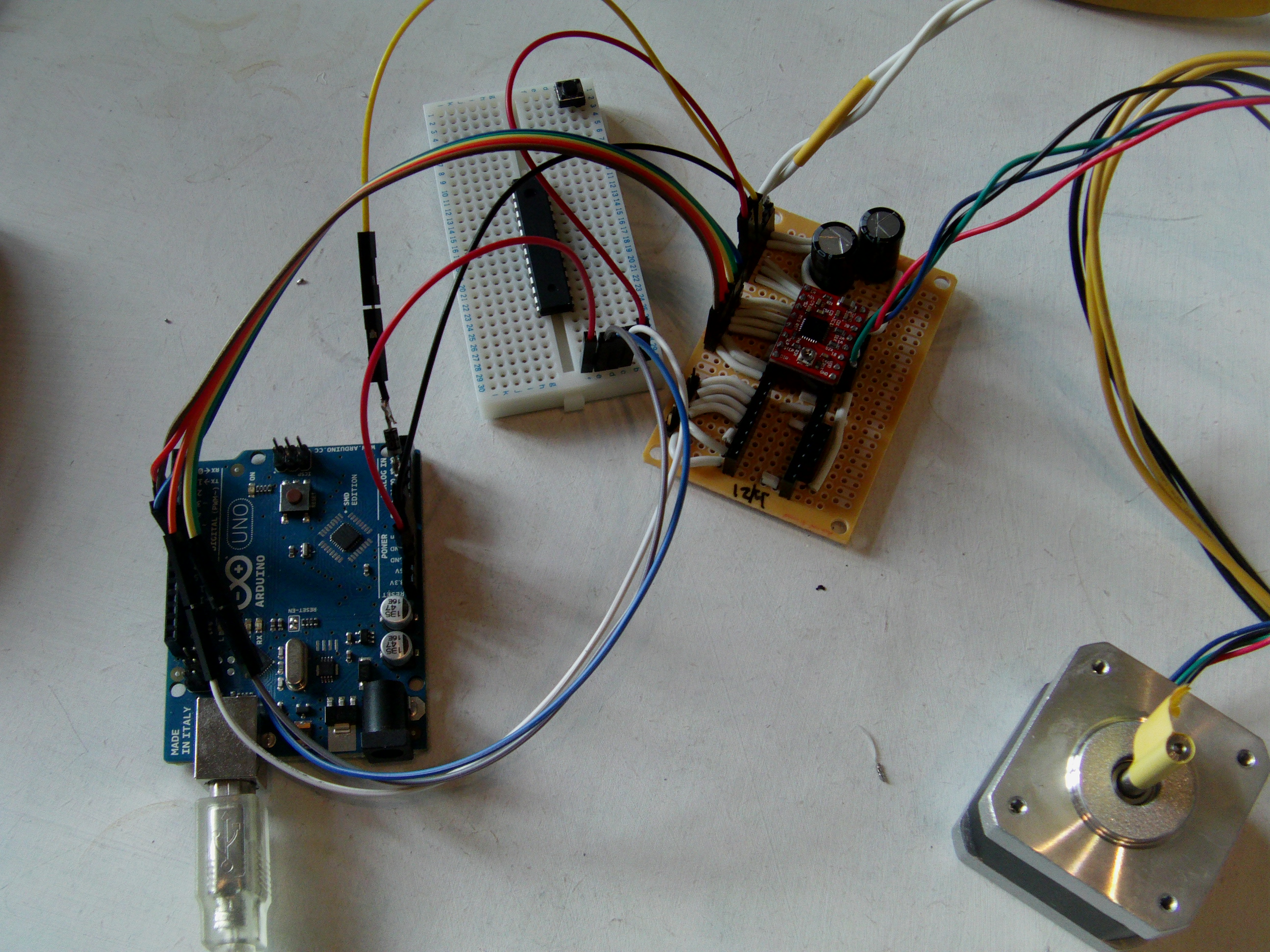
New driver board (the breadboard is just a 5v rail while I change the code to use different stepping methods)
Next steps will be to continue working on the code , Might move to an Arduino Mega so i can use a touch screen too.