ONLY DO THIS IF YOU KNOW WHAT YOUR DOING!!!!!!!
So I’m modifying an old ATX12v PSU for my PSU. It should be good as it has a 12v and 5v rail with suitable current ratings, for the laser, steppers and everything else that’s going into the project. My brother said I should just get a 12v supply then regulate it down to 5v as needed but simply put – this is more fun and cheaper.
I’ll be using the +12v rail for the steppers and the laser diode, oh and some other bits,
the +5v for the logic side of things (with the +5vsb for something maybe too),
I wont be needing the -12v, -5v or the +/-3.3v rails.
I’m not sure what my PSU is but the
- Yellow wires are +12v,
- Red wires are +5v,
- Black wires are common or ground,
- Orange are +3.3v,
- Blue wire is -12v,
- Brown is 3.3v sence,
- Green is PS_ON#,
- Grey is PWR_OK,
- White is -5v,
- Purple is +5vsb,
Which is the standard colour coding as of the ATX12v v1.1.
First thing I did was strip out some unnecessary wires, a few of the grounds and the 5v back at the pcb level and also getting rid of the molex connectors that are designed to connect to the mobo, hard drives ect. I kept the ‘p4’ connector on it’s tails as I thought I might use this specifically for the laser.
Next I connected the wires up into connector blocks as required.
- The orange and brown wires into one block. This is so the the power supply wont shut-down due to thinking that the 3.3v has a short to ground.
- The yellow wires together,
- The red wires together,
- The green and black wires together,
- All other wires are loose at the moment but insulated from each other.
Then I measured the voltages from the ground to each rail I would be using. 5v came up at exactly 5v, 12v at 11.7v, and 3.3v at 3.2v, so pretty accurate under no load.
I also attached a 12v fan over 5v/GND to provide some load to the 5v while testing the 12v out. Eventually I’ll put a resistor on this as discussed in the third reference, but it’s still in the post.
Below is me testing out a stepper motor: http://crazy-logic.co.uk/archives/390.
You can see my plating of the wires to try and keep things nice and neat. Here the h-bridge and arduino were driven from the 12v rail.
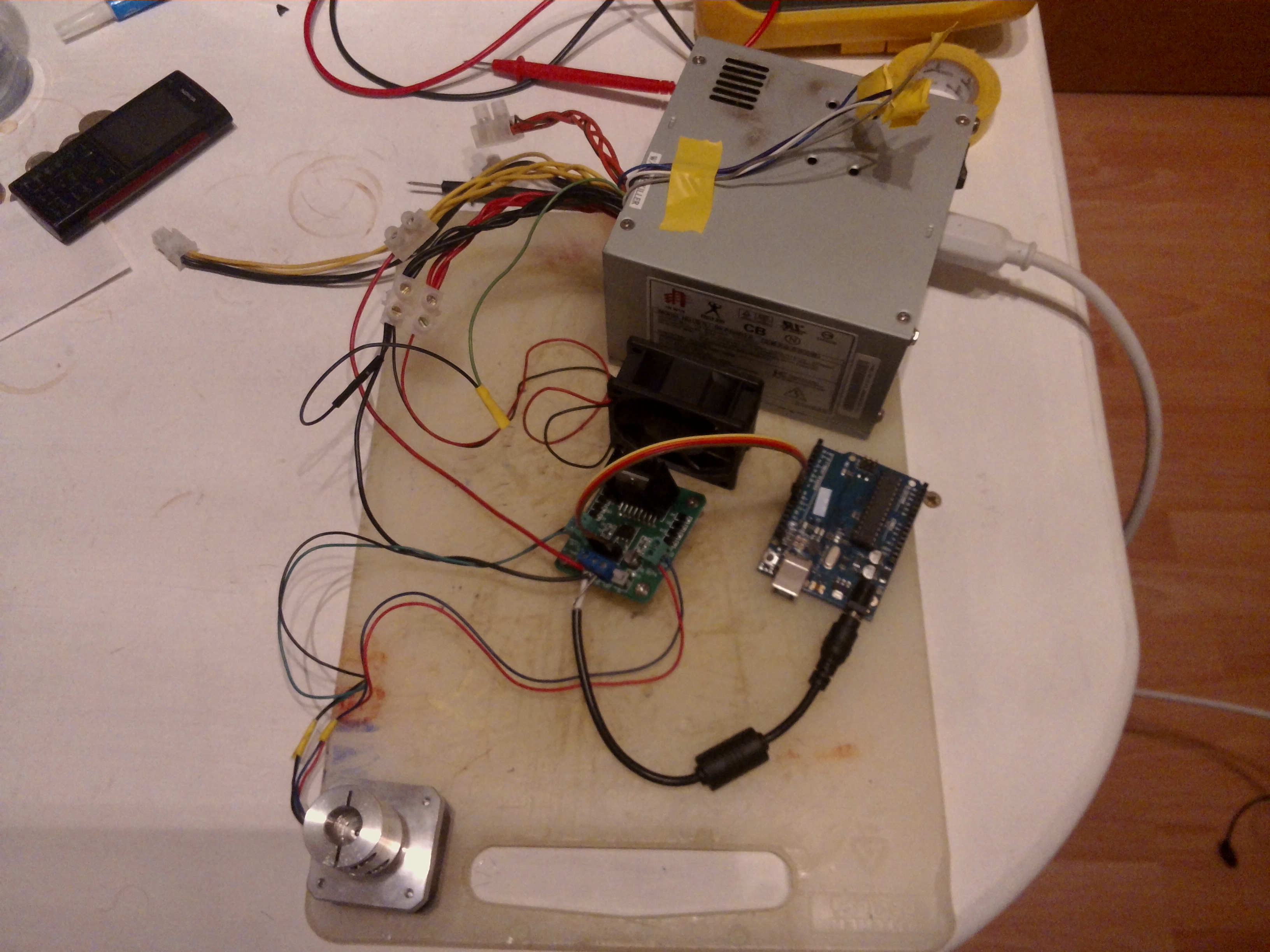
12v stepper motor arrangement
An update: I’ve added the resistor and a low voltage power switch.
References
http://www.formfactors.org/developer%5Cspecs%5CATX_ATX12V_PS_1_1.pdf
http://www.formfactors.org/developer%5Cspecs%5Catx2_2.pdf
http://web2.murraystate.edu/andy.batts/ps/powersupply.htm